
If you’re interested in electrical engineering, you’ve probably come across the terms “resistance,” “reactance,” and “impedance.” These concepts are fundamental to understanding how electrical circuits work, and they’re essential for anyone looking to design or analyze electrical systems.
In this blog post, we’ll explore these concepts in depth, discussing how they work and how they’re used in electrical engineering. We’ll also look at some practical applications of these concepts and how they can be used to design and analyze electrical systems.
So if you’re ready to take your understanding of electrical circuits to the next level, stay tuned for our in-depth discussion of resistance, reactance, and impedance.
What is Impedance?
Impedance is a measure of the opposition that an electrical circuit presents to the flow of an alternating current (AC). It is a complex quantity that includes both resistance and reactance, which are two components that affect the flow of AC differently.
What is Resistance?
Resistance (R) is the measure of opposition to the flow of current in a circuit due to the material properties of the conductors. It is measured in ohms and is the same for both AC and direct current (DC) circuits.
What is Reactance?
Reactance, on the other hand, is a measure of opposition to the flow of AC in a circuit due to the presence of inductance (L) or capacitance (C) in the circuit. Inductance opposes changes in current flow, while capacitance opposes changes in voltage. Reactance is also measured in ohms, but it varies with the frequency of the AC signal.
Impedance (Z) is the total opposition to the flow of AC in a circuit, taking into account both resistance and reactance. It is a complex quantity because it has both a magnitude (absolute value) and a phase angle, which describes the time relationship between the voltage and current in the circuit.
Impedance is represented by the following formula:
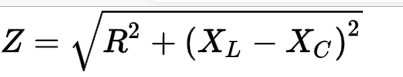
where
 | = | impedance |
 | = | resistance |
 | = | inductive reactance |
 | = | capacitive reactance |
The phase angle (θ) of the impedance is given by:
θ = tan-1 (X/R)
Impedance is an important concept in electrical engineering, especially in AC circuit analysis and design. It is commonly used to describe the behavior of components such as resistors, capacitors, and inductors, as well as more complex circuits and systems.